How to build a Lumenier QAV210
It’s time for another build! This time we’ll be building a Lumenier QAV210. This frame has been out for a few months now. At first I wasn’t sure if I was going to get it but so many readers were asking for custom parts and raving about it. Good thing I listened because this is my new favorite frame!
What makes the QAV210 so great? If I could sum it up in one word it would be fun! It’s small but still big enough to use 5″ props. The small size makes it super nimble with a good power to weight ratio. I’ve only been flying with a 3s setup and it’s plenty fast for me. 4s on this small frame would be a handful. Not only is it fun to fly, it’s easy (easier) to build.
I wanted to build some before I make the build guide just to optimize the build process. So after building about 10 of them, I’ve found this is the easiest and of course cleanest way to build the QAV210. Let’s get started!
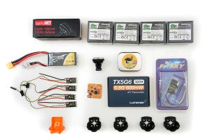 Lumenier QAV210 Build List
- Lumenier QAV210
- Naze32 acro (rev6b) flight controller – As of this post, it’s the most current version
- OSDoge – running MWOSD 1.5
- FrSky D4R-ii – Receiver
- DYS XM20A ESC x 4
- Cobra 2204 2300kv motors x 4
- Lumenier 5.8GHz 600mw Video Transmitter
- HS1177 600TVL Cased Video Camera
- Spironet Antenna
ESC
DYS XM20A ESC use the Silicon Labs microprocessor chip and runs at a whopping 50MHz (BL20A run at 16MHz) so it allows for faster processing speed. This means it can use higher KV motors and is kind of like raising the redline in your car. It can handle higher RPM. These come pre-flashed with BlHeli 14.3, dampen light and one shot enabled. So you don’t have to do any programming yourself. The XM20A come in two versions, V1 and V2. Both versions are the same except V2 come with pre-soldered motor wires and the V1 do not have the wires. We’ll be using V1 because we’ll be soldering the motors directly on to the ESC. This will save us time of removing the motor wires from the ESC.
Motors
I’m using the Cobra 2300kv motors in this build. For a quad this size 2300kv motors will provide plenty of thrust on 3s. You can use almost any 2300kv motors like the T-motor 2300kv or the new EMAX RS2205 2300kv. I was going to use the EMAX but I haven’t gotten them yet. Anyway, you can’t go wrong with Cobra motors.
Custom 3D Parts
- Motor Guards – ever since I started using these I have yet to lose a motor.
- d4r-ii mount – on such a small frame, this is the best solution for mounting the receiver
- QAV210 Sliders – this the landing gear and a front mini bumper
- VTX Brace – protect that SMA connector
Other components used
- Fatshark FPV goggles. These new Dominator SE come with the 5.8ghz RX module, faceplate with fan to dissipate the fog and built in DVR to record the sweet flights.
- FrSky Taranis X9D on firmware (2.0.17). Mine is not the new X9D plus but if you are running the same firmware as mine the programming will be the same.
- Tattu 3s 1550mah 75c Race battery
- Battery charger – I use the HiTec X4, it’s basically 4 chargers in one with a built in power supply. Good if you fly a lot. It can charge 16 1300mah batteries in about 1 hour. Or if you don’t need a big beast like the HiTec, I started with this Tenergy Balancing Charger and works fine. You can use a balance board and charge 3 1300mah batteries at once.
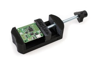
Useful tools for the build
- Weller WESD51 Digital Soldering iron. Here’s the analog version. If you’re never soldered before check out this post on how to solder. It’s not hard and actually pretty fun.
- Soldering vise – handy device to make soldering easier
- Here’s my secret weapon to making ultra clean VTX and Camera wire harnesses. The HT-225D Crimping tool. Instead trying to splice, solder and cover tiny wires, this little gem makes connecting video transmitter and camera cables so easy. I would easily pay double the asking price of $23 for this tool. You will need some 2.54mm Female pin connectors for this.
- Small tweezers – must have for building quads. It will save your fingers while soldering and get to hard to reach places.
Miscellaneous Items
- Heat Shrink for the ESC
- Buzzer – for the discovery buzzer and low voltage warning
- 3 wire servo cable
Build Kit
I’ve put together a kit with the components and all the miscellaneous parts needed to build this quad. It will even include the cheat sheet* used in the video along with the Cleanflight backup file, MWOSD backup file and Taranis bin file that already has RSSI and all the switches programmed. Check out the Lumenier QAV210 Build Kit in the store.
*The cheat sheet is only for people who buy the kit or the frame from the store.
Lumenier QAV210 Build Plan
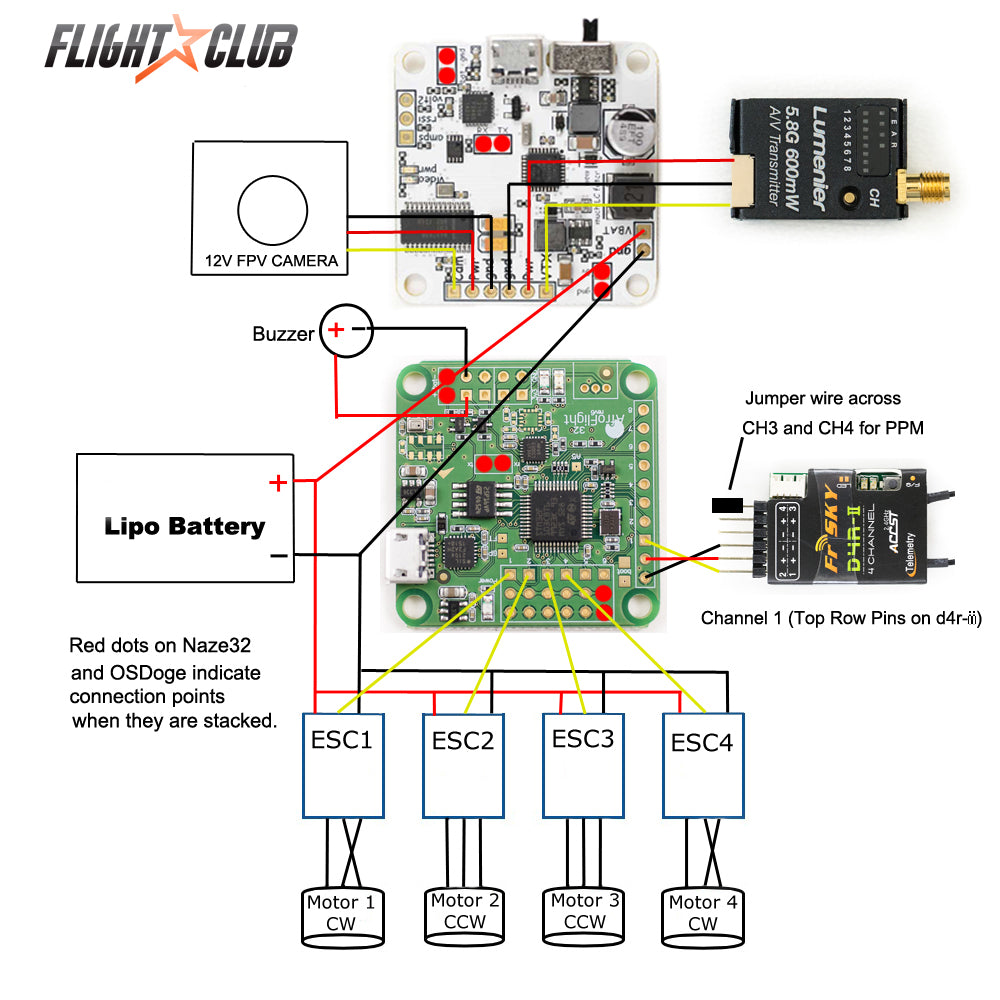
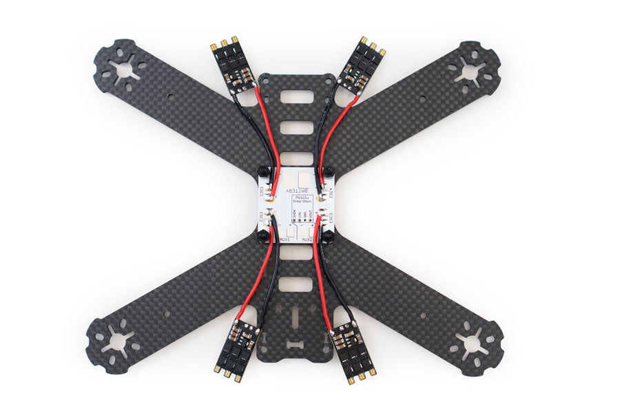
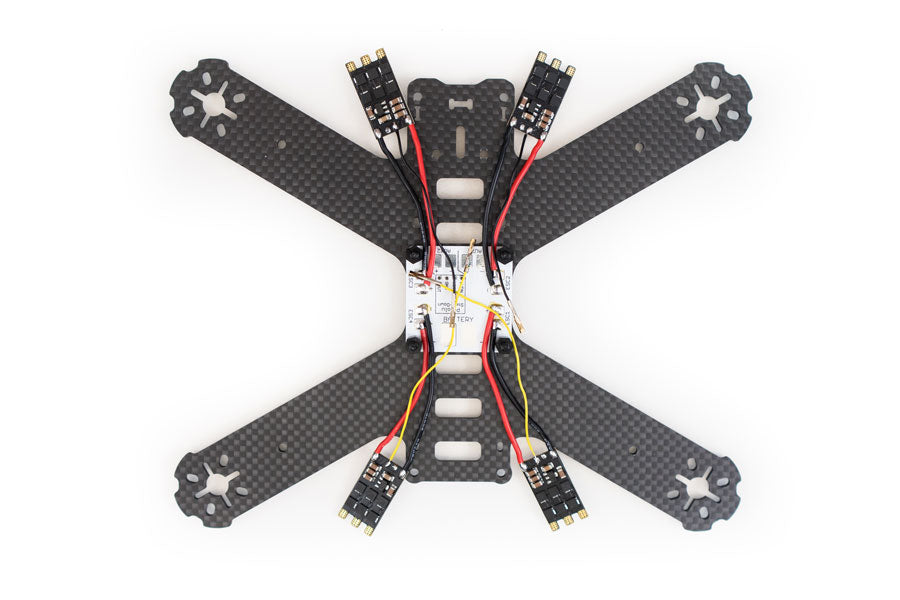
This will be the build plan for the QAV210. We’ll be using the DYS XM20A OPTO ESCs. Notice how the motor wires are connected to the ESCs. Motors 1,4 will have two wires crossed and motors 2,3 will be a straight connect. The crossed wires reverses the direction the motors spin. OPTO means they do not have a built in BEC (battery eliminator circuitry) to provide the 5v needed to power the Naze32. The OSDoge board will provide power for the Naze32 on the +/- on input 6. The OSDoge will also provide the on screen display (RSSI, battery voltage, flight time…etc), LC filter for the video transmitter and camera. The LC filter cleans up the power spikes from power so it’ll give you a clean noise free image in your goggles. We’ll be using the FrSky D4R-ii running PPM. PPM allows you to output 8 channels from one wire. Sounds confusing but I’ll explain what this all means during the build video.
Note: If you are using the EMAX RS2205 2300KV motors, the way they are connected to the ESC are opposite to what’s in the schematic below. Motors 1, 4 will be straight and motors 2, 3 will be crossed.
We will be mounting the Naze32 with the arrow pointing to the rear of the quad. This will allow easy access to the USB port on the left of the quad. When stacked with the OSDoge, this will make the camera and video transmitter input headers point to the front of the quad. The USB for the OSDoge will be difficult to reach but after you program the OSDoge you’ll most likely never need to access the USB anyway. I gave priority to access to the Naze32 USB since it will be needed more. That’s one crappy thing about the rev6 Naze32 is that the USB doesn’t match the OSDoge board. With the Naze32 facing the rear, make sure to adjust the YAW correction in Cleanflight to 180. I’ll show this in part 2.
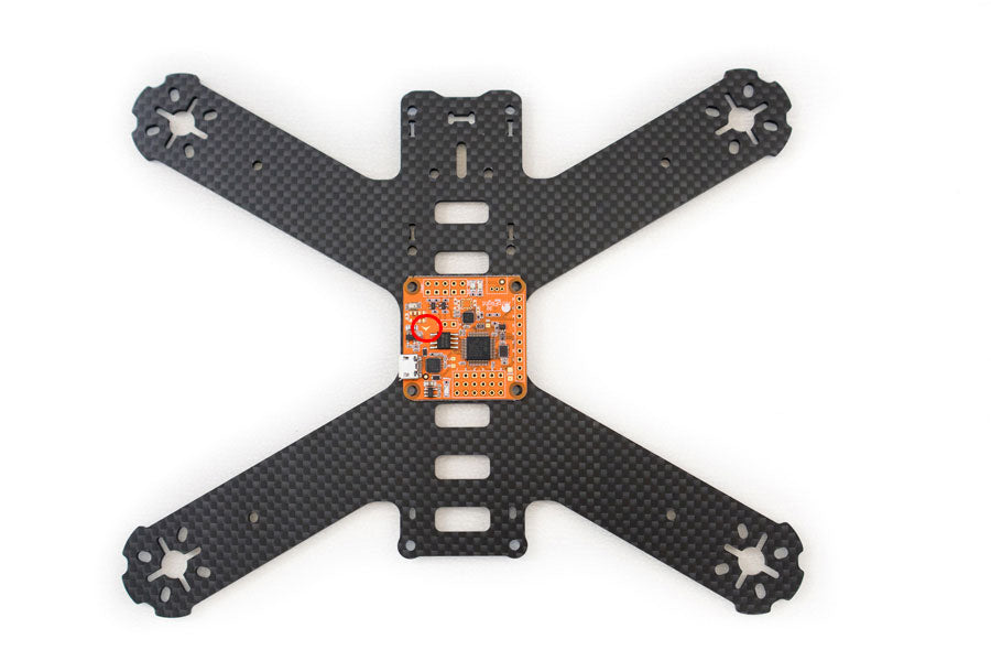
Mount the PDB (power distribution board). Use the included 6mm nylon standoffs and a M3x8 screw. Make sure you do not over tighten the screw. This will introduce too much vibration to your Naze32 and you will develop a hover drift. I’ve notice with the newer batches of Naze32 boards I’ve gotten they are much more sensitive to vibrations than previous batches of boards. I use some blue loctite and lightly tighten the screw. The key here is to not over-tighten the screws mounting the Naze32.
A good thing about using the XM20A V1 (if you want motor wires get V2) are that it doesn’t come with motor wires pre soldered. Since the XM20A come pre-flashed with the latest BlHeli firmware, dampened light and OneShot auto detect, there’s no programming needed. So all you need to do is cut off the heat shrink and remove the signal and ground (yellow and black) wires off.
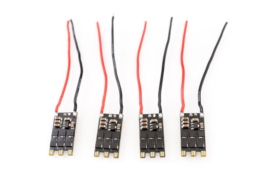
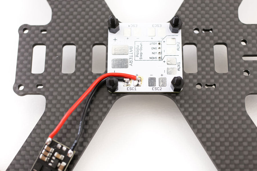
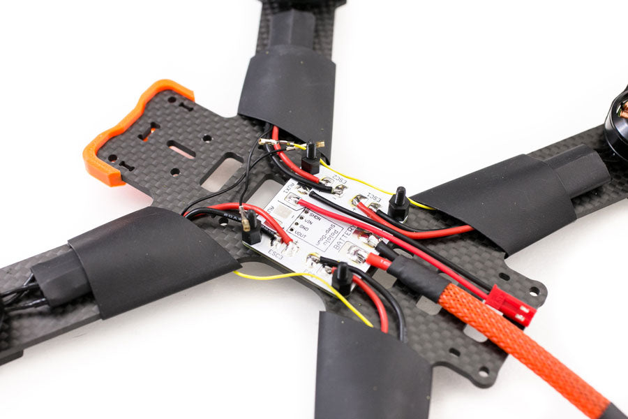
Measure and cut the power and ground wires on the ESC to prepare them to be soldered to the PDB. Use the cheat sheet if you are using the kit for the length of wires. All the PDB does is distribute the positive and negatives to different devices that need power. Solder the red to positives and black to negatives.
Now we’ll prepare the Naze32. Solder a 4pin right angle header for the ESC inputs, the buzzer header and a 3 pin servo wire for the receiver. (these headers are included in the kit). You can use wire cutters to make these headers with with the 3×6 right angle header that come with all Naze32 with right angle headers. It may be messy but it works.
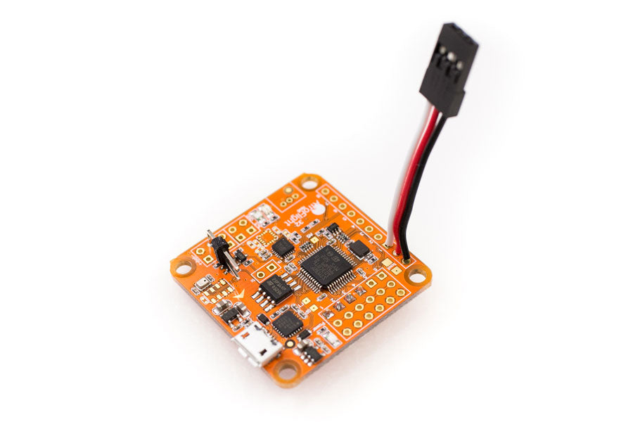
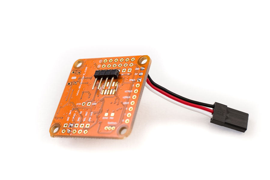
Next get two of the signal wires you took off the ESCs and remove the wires from the plastic housing. If you don’t have a 4 pin connector (included in the kit), you can take the 3pin connectors and cut 1/3 off it. Then you’ll have two 2pin connectors. The color of the wires doesn’t matter as long as you connect the correct ESC to the correct outputs on the Naze32. See diagram.
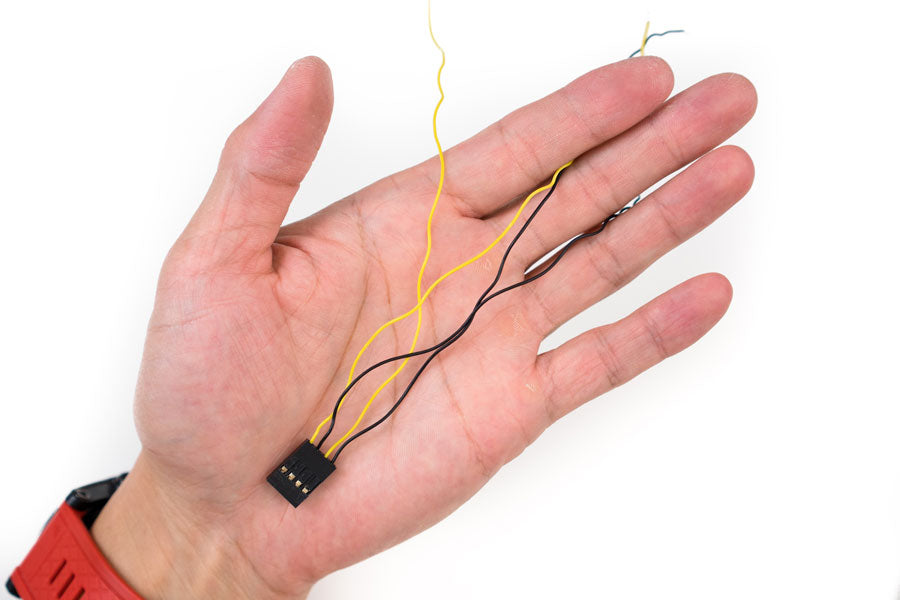
Plug the wires into the Naze32 and put the Naze32 on the quad. Measure out the length of signal wire for ESCs 1-4. Make sure the correct signal wires are going to the correct ESC. Cut and solder on to the ESCs. Use the cheat sheet for the correct length of signal wires.
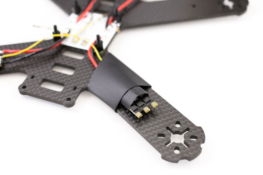
Now you can slip on the heat shrink for the ESC and if you are using the 3/4″ heat shrink for the arms. The 3/4″ heat shrink is just to make the build look neater. Do not shrink them up until after you test the motor directions in part 2 of this build.
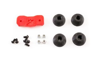 The landing gear that comes with the QAV210 are terrible. They are 10mm standoffs screwed on with a 6mm screw. You can take these and throw them in the tall grass right now because that’s where they’ll end up. I designed some 3D printed sliders that are mounted using a M3x10mm screw with a nylon locknut. You’ll never have to worry about them falling off.
If you using the sliders, now is the time to install them. They must be installed after you put the heat shrink on the ESC and before you mount the motors. Once you mount the motors you won’t be able to access the landing gear hole because it’s under the ESC. Another reason to use the sliders. If you lose a standoff you’ll have to unmount your motor to get to the landing gear hole.
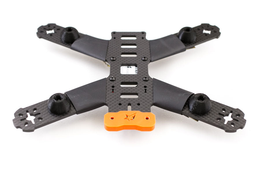
Now we can install the motors. I highly recommend using the motor guards. I haven’t lost a single motor since I started using these on all my quads. I’ve smashed into trees at full speed with no damage to motors. Of course the motor guard broke but that’s the point. They are designed to break so it can save the more expensive parts. Especially if you are running motors that are sometimes hard to get like these Cobra 2204 2300kv motors. Your quad could be on the bench for 2 months before you can get replacement motors.
Mount the motors using at least two screws. The reason for that is if you only use one screw the motor could be crooked when you measure the amount of wire you need to reach the ESC. When you go and mount the motor you may end up with not enough wire. Then you’re screwed.
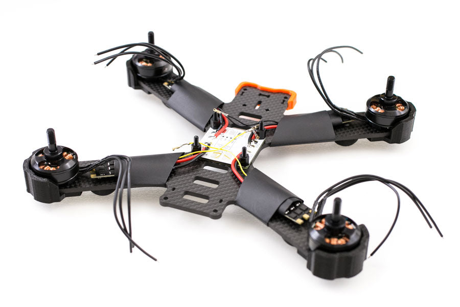
Once you have the motor wires cut to length, tin the wires and ESC pads. Notice how motor 1,4 have two wires crossed and motors 2,3 are straight across to the ESC (see schematic and image below).
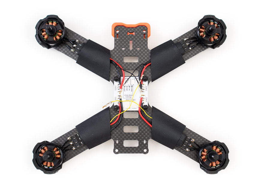
After the motors are soldered on, slip the heat shrink over the ESCs but don’t shrink them. The idea is to prevent the bare ESC from touching the conductive carbon fiber. You don’t want magic smoke.
Next install the included XT60 battery cable. The XT60 cable comes pre-tinned but I don’t know why that solder is really hard to melt. I find it helps if you put your own solder on the cable. It makes it much easier to solder on to the PDB. Before you solder it on the PDB make sure you put the little yellow grommet on the cable. The grommet keeps the XT60 cable in place on the top plate.
If you are using the cheat sheet you can cut and solder the VBAT cable on AUX1 on the PDB. If you aren’t using the cheat sheet you’ll solder the VBAT after you’ve mounted the OSDoge. Plug in the VBAT in the board, measure, cut and solder.
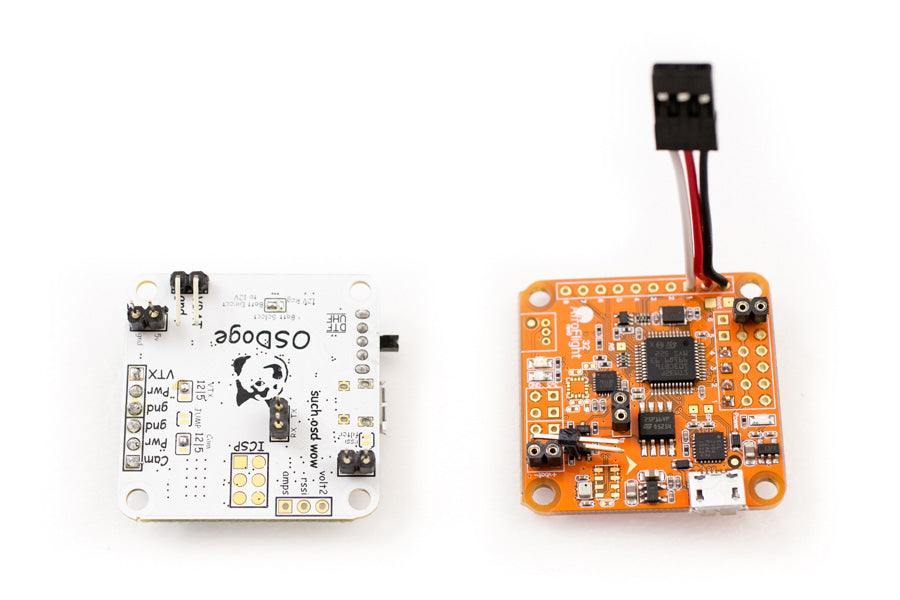
I won’t go super in the details on making the OSDoge/Naze32 stack because I’ve done two other posts on it, OSDoge/Naze32 setup and OSDoge MWOSD 1.5 update.
Now solder the 1×6 right angle header on the top facing in and 1×2 right angle headers on the bottom facing in on the OSDoge board. Put the male/female headers together and put them in the +/- on channel 6, TX/RX and VBAT on the Naze32. Stack the OSDoge on top of the Naze32 and solder the pins.
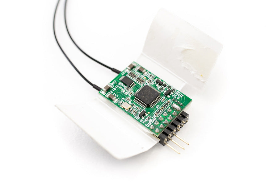
This step is not totally necessary. When building, flying and crashing racing quads, so many things can go wrong. I try to eliminate as much room for error as possible. To put the D4R-II in PPM mode, you need to connect the signal leads on channels 3 and 4. The RX comes with little black square jumper leads. These things always come loose and eventually fall off. To eliminate this problem I just put a solder bridge across 3 and 4. That way you’ll never have to worry about the jumper. Also I clip all the pins off the RX that will never be used. Sometimes the RX will slide forward and the metal pins will touch the Naze32 and cause damage. Cut them off and eliminate another issue.
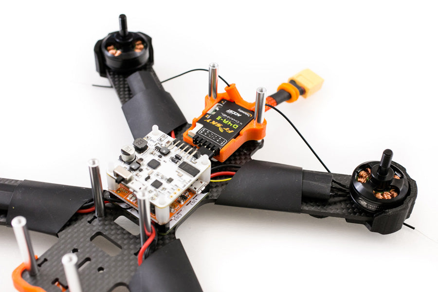
I’ll be using a custom QAV210 d4r-ii mount for the RX. Thread the antennas through the tubes. The mount will slide on the the rear standoffs.
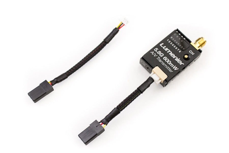
Now we will install the FPV camera and VTX. Use the two camera plates that came with the QAV210 to mount the cased camera. Plug in the camera wire and tilt the camera pointing up. You want to do this because tilting it up will require more wire. You don’t want to end up with not enough wire to reach the OSDoge. Measure and cut. If you aren’t using the crimping tool, you’ll need need to splice the three wires onto a 3wire servo wire to connect to the OSDoge. Do the same for the VTX. See video for what wires to use on the Lumenier 600mw VTX. If you are using the crimping tool, you’ll end up with two super clean FPV cables.
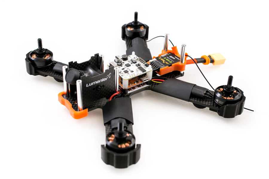
So this concludes part 1 on the build. Part 1 is all the physical build, part 2 (coming soon) will be flashing the Naze32 with BetaFlight, programming the Taranis with switches and setting up RSSI, binding the D4R-II and setting up the OSDoge.
If you found this post helpful, it would be super cool if you purchased the components from my store or purchase items from my Amazon links. These posts are expensive and take a loooong time to make so the purchases make it possible for me to keep making them. Thanks in advance, I greatly appreciate it 🙂

